
Have you ever wanted to know how fast something is moving? Maybe you've wondered just how fast that car was going as it flew past your house. Maybe you want to clock your kid's soccer kick... There has got to be a way to calculate speed using a webcam!
To get speed all we need is distance and time. So if we took two pictures of an object as it is moving, and knew the exact time they were taken we could just measure the distance the object moved between the two shots and viola!

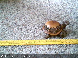
Using the timestamps on the photos, our turtle appears to have moved 8 inches in 28 seconds. Hmm... that's 0.2857 inches per second, which converts to 0.01626 miles per hour! Wow, that's actually pretty good for this type of turtle.
This would be pretty easy if everything were moving along a ruler, but wouldn't it be great to get the distance somehow by simply counting the number of pixels between the two positions of the objects in the pictures, or better yet having the computer do this for us... Now we're talking!
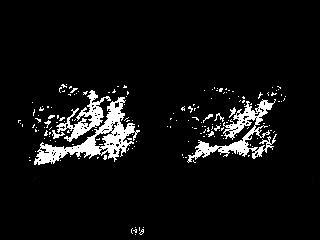
How can this be automated? How can you tell (or how can your computer tell) if an object is moving? One way is to compare multiple photos and see whats different. Photos are made of pixels of course. Each pixel has a number assigned to it and this determines what color it will be. We could have our computer compare photos in grey-scale by subtracting one photo from the other. It would subtract the values of each pixel from its corresponding pixel on the other photo. If the pixels are exactly the same in each picture, they would have the same value and the difference would be zero, which is black. If there is any change, the difference would something other than zero (lighter colors).

OK now we're on to something! you can see the outline of the turtle in its' two positions. The black part of the picture is pixels that were zero, the grey and white are non-zero. What else is in the picture? You can see some white in the bottom center of the image.This is the part of the timestamp that changed from the first to the second image. You can also see some shadow from the turtle. These are things we will have to pay attention to as we develop our speed measuring application.
 Next we will try to clean it up a bit. We need to ignore some of these dark grey colors which represent a small amount of difference, and focus on the brightest white pixels which represent substantial difference. We can 'threshold' the picture and tell the computer to make everything below a certain value black, and everything above that value white. Grey-scale photo pixels can range from 0-255. In the next picture everything that was below 110 is now 0 (black), and everything above 110 is now 255 (white).
What now? Well it just so happens that there is a tool intended to help us crop photos that will identify the left-most or right-most non-zero pixel coordinate in a picture. If we ran that on this turtle image, it would give us the position of the head of the turtle on the right, and the tail of the turtle on the left. This doesn't help. We need to measure head to head.
Actually from this one picture we can't easily make the computer measure the distance the turtle moved. What would make this easier? What if we had a third 'baseline' photo that we could compare the two photos to? We could compare it to a photo with no turtle and that would work. But this would only work if the camera and everything in the frame of view remained exactly the same. If the camera moved even a tiny bit, you would need to take a new baseline photo. In fact, we may as well just make our speed measuring application take a baseline photo every time it is ran. Lets get a series of three pictures now and compare picture 1 and 2, and then compare 1 and 3.


Now if we use that cropping tool (ignore the time-stamp for now) to help us identify the left-most and right-most pixels in these two pictures we would get something like:
Photo 1: left = 0, right = 165
Photo 2: left = 0, right = 315
If we find the difference between the left bounds we get 0 - 0 = 0. The difference between the right bounds we get 315 - 165 = 150. How could a computer know which way the turtle is moving and which number is the correct one to use? This is pretty simple, its the larger answer, 150. The side of the photo the turtle came from will always be near zero because it represents the first photo, the baseline photo, in both the second and third photos. So our turtle moved 150 pixels between photos 2 and 3! And all of this is something that a computer can easily handle doing on its own - automated.
Now lets throw this concept into action. First we need pictures! YawCam makes a free webcam software that has a nice motion detection feature as well as the option to take a series of photos at high speeds.
There are several things we will need to do in order to set up YawCam for our project. We need to set the directory we want it to save pictures to. When YawCam opens, select Motion Detection from the Window Menu.

From the Motion Detection Window we can go into the Actions tab and set the directory and make it save photo files with the time down to the milliseconds in the file name. The version I downloaded already had time down to the millisecond (MS). Also we can set the number of images we want (3) and the time between images. This number will need to be adjusted so that it is fast enough to get three images before the object is gone from the field of view, but not too fast so that the object does not appear to move much. I am using 70 ms for mine.

Now back in the Motion Detection Window we will go into the Settings tab. Here we need to set up the actual motion detector. We need to define the area that YawCam will detect motion within. We also need to set the sensitivity. This may take some playing with to get it working well for you.


It is important that the camera is aiming perpendicular to the path the object will be traveling on. When you get YawCam set up and enabled, it should produce 3 image files in the directory you chose every time an object moves across the screen. There will be times when something else moves and triggers your motion detector. Try to minimize the detection area to where not much else could move.
Now we need the code that will analyze the images. My code is written in Python so you will need to install Python as well as Python Imaging Library for the version of Python you installed. I wrote the script in Python 2.4 but you may want to just download the latest version and give it a try.
Once Python is installed you simply create a text file (New Text Document.txt) and rename it to ImageDiff.py. Now you open it for editing by right clicking and selecting edit. Just open it and paste the code from below. The ImageDiff.py file should be in the same directory with the images. I am not going to explain all of the code in this blog entry but it is heavily commented if you are interested in seeing how it works.
import Image, ImageChops, os, glob, ImageFont, ImageDraw

# Requires Python Imaging Library (PIL)
#     Download at http://www.pythonware.com/products/pil/
# Requires YawCam
#     Download at http://www.yawcam.com/download.php

# YawCam should take an array of 3 photos when the motion sensor is activated.
# The camera should be pointed perpendicular to the objects path.


# CalibrationFactor is the multiplyer to go from
# Pixels per millisecond to your desired units (MPH, KPH, m/s...)
# This has to be calculated by running this script on objects
# with known speeds several times and taking an average. Your motion
# detection area (defined in YawCam) should be centered within the picture so that
# left-bound and right-bound objects get their 2nd and 3rd pictures in the same region
# of the frame.

# Formula:
# CalibrationFactor = (known velocity / velocity inicated on output photos) * Current CalibrationFactor Value
# Set CalibrationFactor
CalibrationFactor = 128.8

# Set desired units
Unit = "MPH"

# Box defines where to crop the pictures so that the timestamp is left off
# for analysis of movement.
box = (0, 0, 320, 218)

# Set to 1 if you want output photos for sensitivity testing, otherwise 0
TestSensitivity = 1
# Use higher value if any white spots are present other than on the object
# Use lower value if there is not enough white to tell where the front of the object is.
Sensitivity = 90

#####################################################################################


# Extracts information about all the files in the directory starting with 'motion'.
filelist = []
fileMS = []
fileS = []
fileM = []
fileH = []
for infile in glob.glob('motion*'):
    filelist = filelist + [infile]
    # the numbers in brackets define where times are found
    # in the file name.
    fileMS = fileMS + [infile[27:30]]
    fileS = fileS + [infile[24:26]]
    fileM = fileM + [infile[21:23]]
    fileH = fileH + [infile[18:20]]

# Counts motion files and raises exeption if there is not a multiple of 3.
FileCount = len(filelist)
if float(FileCount)/float(3)-int(FileCount/3) <> 0:
    print 'The number of files is not divisible by 3.'
    print 'Photo software must be set to capture 3 images'
    print 'each time motion is detected.'
    h = raw_input('press enter to quit')
    raise NameError('Number of files not divisible by 3')


# Asigns variables a,b,and c to designate the 1st, 2nd and 3rd photo of each set.
for x in range(1,(FileCount/3+1)):
    a = x*3-3
    b = x*3-2
    c = x*3-1
    Start = int(fileMS[b])+int(fileS[b])*1000+int(fileM[b])*60000+int(fileH[b])*3600000
    End = int(fileMS[c])+int(fileS[c])*1000+int(fileM[c])*60000+int(fileH[c])*3600000

    Time = End - Start
    if Time <0:
        # Adds a day (in MS) if the end time falls in the next day.
        Time = End + (3600000*24) - Start

    # Converts to greyscale and crops to remove timestamp. Timestamp must not be visible.
    im1 = (Image.open(filelist[a]).convert("L")).crop(box)
    im2 = (Image.open(filelist[b]).convert("L")).crop(box)
    im3 = (Image.open(filelist[c]).convert("L")).crop(box)

    # compares the photos and makes new pictures where changed pixels are white and
    # unchanged are black.
    diff2 = ImageChops.difference(im1, im2)
    diff3 = ImageChops.difference(im1, im3)
    EvalPic2 = ImageChops.invert(Image.eval(diff2, lambda px: px <= Sensitivity and 255 or 0))
    EvalPic3 = ImageChops.invert(Image.eval(diff3, lambda px: px <= Sensitivity and 255 or 0))

    # Saves copies of the above photos if needed for testing.
    if TestSensitivity == 1:
        EvalPic2.save("Test2_" + filelist[b], quality=100)
        EvalPic3.save("Test3_" + filelist[b], quality=100)

    # Finds the difference in x-axis coordinates of the leading edge of each photo.
    # If the object is moving left, the difference in left leading edges will be greater.
    # If the object is moving right, the difference in right leading edges will be greater.
    # This is because the trailing side of the photo is always the same in each photo,
    # it is where the object was in picture 1 (or picture a).
    L = EvalPic2.getbbox()[0] - EvalPic3.getbbox()[0]
    R = EvalPic3.getbbox()[2] - EvalPic2.getbbox()[2]
    Speed = max(L,R)

    # Prepares the string for printing on picture. Number of decimal places is set here.
    Vel = ("%.1f" % (float(Speed)/float(Time)*CalibrationFactor))
    txt =  str(Vel + " " + Unit)

    # writes the velocity text onto the picture
    picTxt = Image.open(filelist[b])
    saveName = "Velocity_" + filelist[b][7:100]
    draw = ImageDraw.Draw(picTxt)
    font = ImageFont.truetype("arial.ttf", 14)
    draw.text((175,222), txt, font=font)
    picTxt.save(saveName, quality=100)
After running YawCam for a while and getting several sets of images in your directory, look at the pictures. You should have exactly 3 sets of images for each object that passed. If each image does not show the leading edge of the object, you need to make adjustments in YawCam. Here's a set of images of a truck driving down my street.


Now you can run the Python script by double clicking it and it will analyse the pictures and produce the following images:


The two black and white pictures are optional output that you can turn off later. We can look at these images and check for problems such as white spots that are not part of the moving object. Also you should be able to tell where the leading edge of the vehicle is. If either of these these things are causing a problem there is a sensitivity adjustment that you can make in the opening lines of the code.

Along with the optional black and white images is the final image of the object with the speed printed on it!
There are several things that need to be set within the Python script. The first thing is the calibration factor. This is calculated by you. Once you have set up your camera and YawCam, you will need to calibrate it by clocking something of know speed several times. For example if you're aiming at a street, drive by several times going exactly the same speed. Take an average of the speed that is printed on your photos and use that in the formula below. The current CalibrationFactor is found in the opening lines of the script and is set at 128.8. Note that the vehicle needs to be in the same lane or position on the street for any reasonable accuracy.
CalibrationFactor = (known velocity / velocity inicated on output photos) * Current CalibrationFactor Value
Below is a screenshot of the opening line of the script showing where you can make adjustments.

The next option that you can set in the script is the units. Changing this simply changes the units label. It doesn't change the speed calculation. Just set this to whatever you used when you calibrated it.
The next option is the box that is used to crop the timestamp off of the picture before analysis. If you are using a version of YawCam similar to what I used, you won't have to change this.
The next option is TestSensitivity. Turn this 1 to a 0 when your black and white output images show no problems.
Adjust the Sensitivity value as the instructions indicate if necessary.
If you're having trouble try shooting in a different location with less things in the picture. Trees cause problems in the wind. The above examples in my front yard had a lot of issues with the tree and with cars being on different sides of the road as they passed. Also my daughter kicking the soccer ball was moving so that caused problems. It would be best to not show the person kicking. You can always test your accuracy by measuring the same thing going the same speed over and over and seeing how much it varies.
Thanks for sharing! I found a link to this on Hack a Day, and I was just getting curious about processing images.
ReplyDeleteTo get ride of the errors of the trees and soccer ball could your program crop the image so the computer only process the area of the road where the vehicle is driving?
ReplyDelete@Friesen Yes that would be a good idea especially if you had the camera mounted somewhere where it would not move and would always be doing the same thing. You could change the crop coordinates in the Python code on the 4th non-comment line starting with "box =". The reason I didn't do that was because my camera was always being moved and it would have taken some trial and error to get the crop just right for each set-up.
ReplyDelete@Mojo I think that that would actually be a realistic use for something like this. For a single vehicle accuracy is probably really low, but if you were constantly taking measurements on a stream of traffic you could probably get a reasonably accurate average.
ReplyDeleteI'm impressed, John. If I was still teaching Algebra it would be a fun project for students.
ReplyDeleteNice work ! You may want to check out my speed camera software from www.raserabwehr.de that can be used to collect and analyze traffic data in your street, and also take radar photos. Let me know if you would like to contribute, i am always looking for help
ReplyDeleteRaspberry Pi brought me here. :) I will see if I can translate this into Linux. Thank you for using Python!
ReplyDeletesir can u tell me ways i can implement using matlab . is this project uses
ReplyDeletelucas kanady algoritm or any other. pls reply
my email address is cusatbook@gmail.com
How can I calibrate this with measuring the distance in the view to get it more accurate. Driving by the field of view several times will not be accurate as car speedometers are off by 5% to 10% depending on the make, model and tire size and wear.
ReplyDeleteThis was just a fun project I did to get a little taste of immage processing and programming. I doubt that it could be that accurate. But if I wanted to be certain of the vehicle speed, I would download a GPS app onto my phone that tells speed. Also I would be carefull to maintain the speed for a good 10+ seconds as approaching the camera to make sure the GPS has calculated the speed more accurately.
DeleteAt $70.00 it really doesn't do much more. I would strongly recommend against people using WebCam Monitor as it is heavily overpriced for it's capabilities.
ReplyDeleteThis comment has been removed by the author.
ReplyDeleteIf after adjusting the sensitivity setting you still have problems with extra white pixels, I would look at what might be causing them. It could be camera movement, movement in the background such as trees or other objects moving. Also I would look at making the box defined in the block of code above the sensitivity adjustment as small as possible, even smaller than the object may be the route to go. For example if the object is something big like a vehicle just a use a narrow strip a few pixels wide along the lane. It does need to be long enough to capture the series of photos though.
DeleteHi John, great post. For a noob programmer like me you did great explaining the code.
ReplyDeleteMy problem in getting it to work was that I am not running on windows so I shelved the project for another day.
That came yesterday. Check out http://hackaday.com/2016/04/03/raspberry-pi-as-speed-camera/ which does pretty much the same as you.
I have not check if the python very different but I just had an idea that maybe a bit of syndication could improve the workings even further?
I see a uhm..... OpenSpeedcam project ;-)
Interesting post. Hackaday posted my speed camera also. http://hackaday.com/2012/05/31/catch-neighborhood-speeders-with-your-webcam/ I would say that this new raspberry cam code looks much better than mine. Mine uses separate cam software that you have to manually start and stop, and then my python code processes all the pics at once. Theirs does everything continuously I believe.
DeleteI copied your script but the application opens and shuts and it doesn't produces any images, whats wrong
ReplyDeleteAgreed, it can't even find a video stream... SCAM. And SPAM, too...
ReplyDeleteThis hasn't been active for over a year but I stumbled upon it while in need of a free way of demonstrating our speeding issues in front of my home. A big thanks for doing the legwork on this, I can verify it works great with Python 2.7 and Pillow. I have made a minor change for my circumstances, my camera is forced to look down upon my road and the calibration was always off for one direction or another. I have added a CalibrationFactorLeft and CalibrationFactorRight to your script and compare the L and R values to determine which calibration to use for determining Vel.
ReplyDeleteThanks so much for writing this and documenting the steps, I really appreciate it.
Can you share what you've learned or built? I'm looking to do the same thing - help control driving in our neighborhood. From reading through the comments here it seems like there's some products out there? Or is it better/easier/cheaper to build one yourself (if you have the know how)?
DeleteAs John said, the code as he wrote it is not meant to be very accurate. The small changes I made were to help compensate for the variance caused by the position of my camera.
DeletePersonally I am just using it to demonstrate to our village council the magnitude of the problem in front of my house.
This comment has been removed by the author.
ReplyDeleteHigh accuracy is probably not possible with this system. If you want to use your results for anything meaningful I really recommend you learn how to calculate a standard error and how to report your results fairly.
ReplyDeletemy free webcam in https://xxxcame.com is a grown-up site including young ladies performing live on their webcams. All charming adolescent young lady cams are allowed to see with the young ladies depending on tips to prop the appear.
ReplyDeleteThe XXXCAME that give free my free webcam is an open wellspring of porn site giving live webcam exhibitions by models, regularly including bareness and sexual movement frequently running from striptease and messy converse with masturbation with sex toys.
One cam young lady from MyFreeCams — usually shortened to MFC - XXXCAME — reached Motherboard after a week ago's article.
The website that gives myfrewebcam has been assessed and thought about articles go for keeping devotees of webcam sex, educated and prepared to lock in.
Is there an app available to catch speeders in my neighborhood speed limit is 25 but cars are traveling in excess of 40 miles an hour?
ReplyDelete